
Mastering LED Package Types: A Comprehensive Breakdown
- 2024-03-11 15:10
- UNITOP
Choosing the wrong LED package type for your project creates problems you'll deal with for years—premature failures, excessive maintenance calls, unhappy clients, and blown budgets. I've seen it happen dozens of times with commercial lighting projects that went with the cheapest option or simply didn't understand the differences between SMD, COB, and specialized packages.
LED package selection directly impacts efficiency, lifespan, thermal performance, and ultimately your project's ROI. From SMD strips delivering uniform retail lighting to high-power COB arrays illuminating warehouse floors, understanding package types prevents costly mistakes that many contractors only discover after installation.
This guide breaks down every major LED package type you'll encounter in commercial projects. You'll learn exactly which package to specify for LED strips, downlights, high-bay fixtures, and specialty applications. We'll cover technical specifications that matter, real-world performance differences, and practical selection criteria based on our experience supplying LED packages for commercial buyers, contractors, and specifiers.
Whether you're retrofitting an office building, designing a new retail space, or specifying industrial lighting, you'll know precisely which LED package type delivers the best performance for your budget and application requirements.
What Are LED Package Types?
LED packages are complete assemblies that transform fragile semiconductor chips into robust, application-ready lighting components through protective housings, thermal management systems, and optical control elements. The package is everything that makes an LED chip usable in the real world.
Understanding LED packages starts with knowing what goes into them. An LED package contains five essential components working together:
The LED die or chip generates light through semiconductor action. This tiny piece of material (often less than 1mm²) is the actual light source but cannot function alone. The lead frame or substrate provides structural support and creates electrical pathways from external circuits to the chip. In SMD packages, this is typically a metal frame; in COB arrays, it's a thermally-conductive circuit board.
The encapsulant material—usually epoxy, silicone, or specialized resin—protects the chip from environmental damage including moisture, dust, and mechanical stress. The phosphor layer converts blue LED light into white or other colors by absorbing short-wavelength photons and re-emitting them at longer wavelengths. Finally, optical elements like lenses, reflectors, or diffusers shape light distribution and control beam angles.
Package type determines five critical performance characteristics. Thermal management controls how effectively heat moves away from the LED chip, directly affecting maximum operating power and lifespan. Light extraction efficiency determines what percentage of generated photons actually escape the package. Installation complexity influences labor costs—through-hole LEDs solder easily by hand while COB arrays require precise mounting and heat sinking.
Reliability and failure modes change dramatically between package types. Individual SMD LEDs can fail independently in an array, allowing partial replacement. COB arrays share a common phosphor layer, so degradation typically affects the entire unit. Application suitability varies widely—what works brilliantly for LED strips fails completely in high-power spotlight applications.
LED packages are classified by three main criteria. Mounting method separates surface-mount (SMD) designs from through-hole types that insert through circuit board holes, plus chip-on-board (COB) approaches that mount bare chips directly. Power level creates natural categories: low-power packages under 0.5W serve indicators and strips, mid-power from 0.5-1W handles general lighting, and high-power packages above 1W serve spotlights, automotive, and industrial applications.
Application focus further distinguishes packages. General lighting packages optimize for white light efficiency and color quality. Display and screen packages prioritize pixel density, viewing angle, and color gamut. Specialized packages target specific needs like horticulture (targeted spectrum), UV applications, or automotive lighting (extreme reliability).
The package you choose creates a cascade of downstream decisions affecting drivers, heat sinks, optics, assembly methods, and ultimately total system cost. A 20W COB package needs constant-current drivers and substantial heat sinking but simplifies optical design. An equivalent SMD array using forty 0.5W packages can use simpler constant-voltage drivers but requires complex array design and individual LED management.
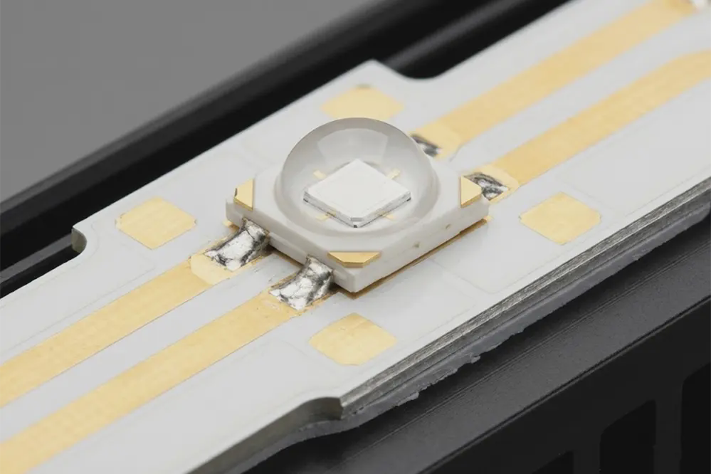
SMD LED Packages
SMD (Surface-Mount Device) LEDs dominate 60-70% of the general LED lighting market for good reason—they hit the sweet spot of cost, performance, and manufacturing scalability. If you're working on LED strips, panel lights, or most general commercial lighting under 1W per LED, you're working with SMD packages.
Surface-mount LEDs are compact packages designed for automated pick-and-place assembly directly onto PCB surfaces. Unlike through-hole LEDs with wire leads, SMD packages have flat contact pads that solder directly to circuit board surfaces. This enables high-density layouts, automated manufacturing, and compact fixture designs that would be impossible with through-hole technology.
The real genius of SMD packages shows up in their size designation system. Those four-digit numbers like "2835" or "5050" aren't random—they specify physical dimensions in tenths of millimeters. A 2835 package measures 2.8mm × 3.5mm. This standardization means you can source compatible LEDs from multiple manufacturers and predict exactly how many will fit in your design.
SMD 2835 became the workhorse of the LED industry around 2015-2018 and remains the most popular size today. At 2.8mm × 3.5mm, it's large enough for good light output but small enough for high density. These packages typically deliver 20-50 lumens per LED at 0.2-0.5W power consumption, achieving 100-130 lm/W efficacy. The 120° viewing angle creates even light distribution perfect for LED strips and general lighting.
I specify 2835 packages for probably 70% of commercial LED strip projects. For typical under-cabinet lighting, 120 LEDs per meter using 2835 packages delivers 1,800-2,400 lumens per meter at about 14-15 watts—excellent output for the power consumption.
SMD 3528 represents the earlier generation of LED strips. At 3.5mm × 2.8mm (note the dimensions are reversed from 2835), these smaller packages produce 6-10 lumens at 0.06-0.12W. They're still manufactured but largely replaced by 2835 for new projects. The only time I recommend 3528 now is matching existing installations where visual consistency matters.
SMD 5050 packages measure 5.0mm × 5.0mm and contain three LED chips in one housing. This tri-chip design makes them ideal for RGB color-changing applications—each chip handles one color. Total power consumption runs 0.2-0.6W for all three chips, producing 15-20 lumens in white light mode. For RGB LED strips in entertainment, hospitality, or architectural accent lighting, 5050 remains the standard. Just note that for pure white light applications, 2835 delivers better efficiency.
SMD 5630 packages at 5.6mm × 3.0mm represent the high-output SMD category. These deliver 50-60 lumens at 0.5W, making them suitable for high-brightness strips and linear fixtures. The larger size means fewer LEDs fit per meter, but each produces more light. I use 5630 when clients need maximum brightness in limited linear space, though proper thermal management becomes more critical at these higher power levels.
SMD 3014 offers a slim 3.0mm × 1.4mm profile useful for edge lighting and ultra-thin applications. At 0.1-0.12W and 10-12 lumens output, they're lower power than 2835 but enable very high LED density—up to 240 per meter in some strip designs.
SMD packages operate at 2.8-3.4V DC with current ranging from 60mA to 180mA depending on size. In LED strip applications, you'll typically see them wired in series strings designed for 12V or 24V constant-voltage operation. Individual SMD packages run at about 3V; string four in series and you get 12V operation, string eight for 24V.
Thermal resistance for SMD packages ranges from 10-25°C/W junction-to-board. This sounds technical but matters practically—it means every watt of power creates 10-25°C temperature rise between the LED chip and the circuit board. High-density SMD layouts require aluminum-backed PCBs or additional heat sinking to keep temperatures under control.
Optical performance includes that 120-140° lambertian distribution I mentioned, available across the full color temperature range from warm 2700K to cool 6500K. Color rendering options now include CRI 70, 80, 90, and even CRI 95+ for high-end retail and hospitality applications where color accuracy matters.
SMD packages dominate four major application categories. LED strip lighting represents 70% of SMD usage—retail displays, cove lighting, under-cabinet task lighting, and architectural accents all rely on SMD strips. Signage and displays including channel letters, backlit signs, and display case lighting use SMD for their compact size and ease of array design. Residential lighting in retrofit bulbs, downlight fixtures, and decorative fixtures increasingly uses SMD packages. Commercial general lighting including panel lights, troffer retrofits, and linear fixtures leverages SMD's cost-effectiveness and manufacturing efficiency.
SMD packages win on six key advantages. They're cost-effective at scale thanks to mature manufacturing and automated assembly—you can buy quality 2835 LEDs for $0.10-$0.30 each in volume. The compact size enables slim fixture designs impossible with older technologies. Wide availability from dozens of manufacturers means you're never locked into a single source. Flexible design options across multiple package sizes let you optimize for specific applications. Good color consistency through established binning practices ensures visual uniformity. Simple integration using standard reflow soldering processes means any competent electronics manufacturer can assemble SMD-based products.
The limitations matter too. Moderate power handling means SMD packages aren't suitable for high-intensity spotlight applications—trying to push individual SMD LEDs above 0.5W creates thermal challenges. Thermal management complexity increases dramatically with high-density layouts; I've seen many failed DIY projects that packed SMD LEDs too densely without adequate cooling. Each LED becomes an individual failure point, so arrays with hundreds of LEDs have higher probability of eventual failures compared to single COB units. Lower efficacy at high power shows up when you try to overdrive SMD packages—efficiency drops significantly above rated current.
Here's practical guidance from real projects: If you need more than 5,000 lumens in less than 500cm² area, seriously consider COB packages instead of high-density SMD arrays. The thermal management becomes complex and expensive with SMD, while COB handles it elegantly.
For a recent retail display project, we specified 2835 SMD strips at 120 LEDs per meter, achieving 1,800 lumens per meter at 14.4W consumption. That works out to 125 lm/W system efficacy, which is excellent for LED strips including driver losses. The client needed 40 meters total, so 4,800 individual LEDs. After two years, we've had exactly zero LED failures and zero maintenance calls—that's the reliability you get with quality SMD packages properly implemented.
COB LED Packages
COB (Chip-on-Board) technology represents a fundamentally different approach to LED packaging that excels in high-power commercial lighting. Instead of individual packaged LEDs placed separately, COB mounts multiple bare LED chips directly onto a substrate and covers them with a single unified phosphor layer. This creates one high-intensity light source rather than dozens of point sources.
The construction difference matters practically. SMD packages are self-contained units—each has its own housing, phosphor coating, and leads. You mount many SMD packages to create an array. COB skips individual packaging entirely. Ten to one hundred bare LED chips get directly attached to an aluminum or ceramic substrate using die-attach adhesive. Wire bonds connect them in series/parallel configurations for desired voltage. Then a single phosphor layer covers all chips, creating a uniform light-emitting surface typically 10mm to 50mm in diameter.
COB packages dominate the 30-40% of commercial lighting market focused on high-performance applications. They own the 10W-200W power range almost completely. When you see quality commercial downlights, track lighting, or high-bay fixtures, there's likely a COB array inside.
Two COB architectures exist with different performance characteristics. Traditional upright COB mounts LED chips face-up on the substrate. Wire bonds sit on the top surface connecting chips to contact pads. Light emits upward through the phosphor layer. This is the standard COB configuration you'll find in most commercial fixtures.
Flip-chip COB represents the advanced architecture gaining adoption in premium applications. Chips mount face-down with electrical contacts directly on the bottom surface touching the substrate. This eliminates top-surface wire bonds, improving thermal performance and optical uniformity. Heat transfers directly from chip to substrate without passing through wire bonds. The emission surface has no obstructions. Flip-chip COB costs more but delivers superior reliability and performance where budget allows.
COB packages scale across wide power ranges. Small COB units at 10-30W typically measure 20-30mm diameter, suitable for standard downlights and track lights. Medium COB at 30-100W and 30-40mm diameter serves larger downlights and small high-bay fixtures. Large COB arrays at 100-200W with 40-50mm diameter handle industrial high-bay and stadium lighting demanding extreme output.
Performance characteristics that matter: COB delivers 100-200+ lumens per square centimeter, much denser than SMD arrays. System efficacy ranges from 90-150 lm/W depending on drive current and quality. The single phosphor layer creates excellent color uniformity—there's no variation between individual LEDs because it's truly one light source. Thermal resistance runs 0.5-2°C/W when properly mounted, superior to SMD arrays.
Operating voltage typically runs 30-40V DC for COB modules. A 36V COB might actually operate anywhere from 33-38V depending on forward voltage variation, which is why constant-current drivers are mandatory. Operating current ranges from 0.3A for small 10W COB up to 6A for 200W arrays.
The optical benefit shows up immediately—COB creates a single point source with 120-130° lambertian distribution. One clean shadow instead of multiple overlapping shadows from SMD arrays. The color mixing is perfect because there's literally one phosphor layer converting all the blue light. No binning needed like SMD arrays where you're combining dozens of individual LEDs that might vary slightly in color.
Let me show you the real difference between COB and SMD through a detailed comparison based on actual project experience:
Power handling: COB excels at 10-200W per unit; SMD works best at 0.06-0.5W per unit. For a 50W downlight, COB needs one package; SMD would need 100+ individual LEDs.
Lumen density: COB achieves 100+ lm/cm² easily; SMD tops out around 20-40 lm/cm² before thermal issues dominate. This density difference is why COB fits in compact downlight fixtures while SMD needs larger areas.
Light uniformity: COB produces one perfectly uniform source; SMD creates a grid of point sources that can appear as individual dots up close. I specify COB for applications where viewing distance might be 2 meters or less.
Shadow patterns: COB throws a single sharp shadow; SMD arrays create multiple softer shadows. For accent lighting where shadow quality matters, COB wins.
Thermal management: COB provides superior heat handling through direct chip-to-substrate contact; SMD transfers heat through PCB traces which creates more thermal resistance. A 50W COB can run cooler than a 50W SMD array in the same fixture.
Assembly complexity: COB is simple—one component plus driver; SMD arrays require placing dozens or hundreds of individual packages. Labor cost advantage goes to COB at high power.
Cost per lumen at high power: COB delivers lower cost above 20-30W; SMD is cheaper for low-power applications. The crossover happens around 10-20W depending on specific products.
Cost per lumen at low power: SMD wins decisively under 5W; COB packages aren't manufactured at these low powers.
Driver requirements: COB demands quality constant-current drivers with 30-40V output; SMD can use simpler constant-voltage drivers at 12-24V for strip applications.
Optical design: COB simplifies lens and reflector design because you're controlling one point source; SMD arrays need complex optics to blend dozens of point sources.
Color consistency: COB is excellent (single phosphor); SMD is good but requires binning multiple LEDs from same color bin.
Maintenance approach: COB is single point failure—entire module replaces; SMD allows individual LED replacement theoretically (though rarely practical).
Best applications: COB dominates downlights, spotlights, and high-bay; SMD owns strips, panels, and distributed lighting.
COB applications break down into clear categories. Commercial downlights represent 40% of COB usage—office ceiling fixtures, retail spotlights, and hospitality ambient lighting all leverage COB's compact high-output advantage. Track lighting systems in art galleries, retail merchandise highlighting, and museums use COB for precise beam control and color quality. High-bay industrial lighting depends on 100-200W COB arrays for warehouse, manufacturing, and distribution center illumination. Architectural spotlighting including facade lighting and accent lighting uses COB when serious output and color rendering matter. Professional lighting for photography, video, stage, and broadcast applications increasingly specifies COB for its superior color quality and single-source characteristics.
Seven advantages explain COB's dominance in commercial applications. Exceptional thermal performance comes from direct chip-to-substrate contact creating the shortest thermal path possible. Uniform light output with a single phosphor layer means no visible individual LEDs and consistent color across the beam. Simplified optics because you're working with essentially one point source instead of managing an array. Higher efficacy at high power compared to SMD arrays operating at the same total wattage. Longer lifespan potential through superior thermal management that keeps junction temperatures lower. Reduced component count means fewer solder joints and assembly steps, lowering failure risk. Professional appearance delivers a seamless light source without visible individual LED dots.
Five limitations require consideration. Higher initial cost per unit compared to individual SMD packages—a 20W COB costs $3-6 while equivalent SMD packages total maybe $2-4. Requires robust heat sink because all the power concentrates in one spot. Single point failure means if the COB degrades, you replace the entire module. Complex driver requirements—you need quality constant-current drivers, no shortcuts. Not suitable for low-power applications because COB packages aren't manufactured below about 10W.
Selection guidance based on real-world experience: Choose COB for applications requiring more than 30W in a compact area with superior light quality. Choose SMD for distributed lighting, low-power applications, or when individual LED replaceability matters. The decision usually becomes obvious once you define power requirements and physical space constraints.
In our commercial downlight projects, we consistently use 20W COB modules achieving 2,400 lumens at 120 lm/W system efficacy. These are flip-chip COB packages with projected L70 lifetimes exceeding 50,000 hours based on LM-80 data from the manufacturer. After installing thousands of these fixtures over five years, we're seeing actual failure rates under 0.2%—that's why we stick with COB for commercial projects despite the higher upfront cost.
Through-Hole LED Packages
Through-hole LEDs represent the original LED package design that dominated from the 1970s through early 2000s. While SMD packages have replaced them in most commercial lighting applications, through-hole LEDs remain relevant for indicators, prototyping, legacy maintenance, and DIY applications where their unique advantages still matter.
Through-hole packages feature two wire leads (anode and cathode) that insert through holes drilled in a circuit board. The leads get bent and soldered from the back side, creating mechanical retention superior to surface-mount packages in high-vibration environments. Standard sizes include 3mm, 5mm (most common), 8mm, and 10mm diameter measured at the LED housing.
The physical construction is straightforward and unchanged for decades. An LED die sits in a small metal cup reflector at the base of the package. The reflector cup improves light extraction by bouncing photons upward. A thin wire bond connects the LED die to one lead while the die itself makes electrical contact to the other lead through the metal cup. The entire assembly sits inside an epoxy lens that protects the die and shapes light output.
Lead length typically measures 25-30mm as manufactured, though you can trim them to whatever length your application requires. The anode (positive) lead is longer than the cathode (negative) lead—this built-in polarity indicator helps during hand assembly.
Lens types create different optical characteristics. Clear lenses produce narrow beams of 10-30° with high center intensity, useful for indicators where you want the LED visible from directly in front but not from the side. Diffused lenses spread light across 40-60° creating softer, more even illumination suitable for general indicators. Colored lenses filter white LED output to specific colors, though most colored LEDs now use colored dies instead for better efficiency.
Through-hole LEDs operate at modest power levels. Electrical specifications include 1.8-3.4V forward voltage depending on color, 20mA standard operating current (though high-brightness versions go to 100mA), and typical power consumption from 0.06W to 0.3W. Output ranges from 0.5 lumens for small indicators up to 20 lumens for high-brightness white LEDs.
Forward voltage varies by color due to different semiconductor materials. Red LEDs run 1.8-2.2V because they use AlGaInP semiconductors. Yellow and amber operate at 2.0-2.4V. Green LEDs need 2.8-3.2V. Blue and white require 3.0-3.6V because they use InGaN semiconductors that need higher voltage for electron excitation. This voltage variation matters when designing circuits—you can't just swap red and blue LEDs without adjusting current-limiting resistors.
Optical performance includes beam angles from 10° to 60° depending on lens design. Output ranges from 0.5 to 20 lumens. Efficacy runs 50-80 lm/W typical, lower than modern SMD but adequate for indicator applications. Colors available include red, green, blue, yellow, white, and RGB multi-chip packages.
Current applications focus on five areas where through-hole advantages still matter. Indicator lights for status displays on equipment, power indicators, and activity LEDs remain the largest application. Hand-soldering accessibility and mechanical retention make through-hole ideal here. DIY and hobby projects including Arduino builds, Raspberry Pi indicators, and breadboard prototyping universally use through-hole because makers can work with them easily. Legacy system maintenance requires through-hole replacements for older equipment where SMD retrofit isn't practical. Simple displays including 7-segment numeric displays and dot matrix arrays still use through-hole in many products. Automotive dashboard indicators in older vehicles (pre-2010) typically used through-hole LEDs.
Through-hole still makes sense in six specific scenarios. Manual assembly or prototyping benefits from easy hand-soldering—you can place and solder through-hole LEDs with basic tools in minutes. Easy hand-soldering required for field repairs or one-off assemblies where automated equipment isn't available. Better mechanical retention in high-vibration environments where the through-board mounting creates stronger physical attachment than surface-mount packages. Legacy equipment repair when replacing existing through-hole parts and the circuit board can't be redesigned. Educational and hobbyist applications where beginners learn electronics using components they can easily work with.
SMD has replaced through-hole in commercial production for clear reasons. Through-hole packages require larger PCB footprint—a 5mm LED needs roughly 8mm × 8mm board space including lead spacing, while an SMD 3528 needs only 3.5mm × 2.8mm. Manual or semi-automated assembly is slower and more expensive than automated pick-and-place machines handling thousands of SMD components per hour. Higher labor costs for manual soldering make through-hole uneconomical in volume production. Limited to low-power applications—through-hole packages top out around 0.3W while SMD routinely handles 0.5-1W. Less efficient use of PCB space means larger boards for equivalent functionality.
The market reality shows the magnitude of this shift. Through-hole LEDs held 80% market share through the 1990s. By 2005, SMD had captured 50%. Today through-hole represents less than 5% of commercial LED lighting but remains stable in the indicators and DIY segments where its advantages still matter.
While we primarily specify SMD for commercial projects, through-hole LEDs remain the practical choice for replacement indicators in legacy control panels where PCB replacement isn't cost-effective. I recently worked with a client maintaining industrial control equipment from the early 2000s—spending $500 on circuit board redesign to use SMD made no sense when $5 of through-hole replacement LEDs solved the problem.
High-Power LED Packages
High-power LEDs fill the critical performance gap between standard SMD packages and full COB arrays. These specialized packages handle 1W to 10W per LED, featuring advanced thermal management and precise optical control. While SMD tops out around 0.5W and COB typically starts at 10W, high-power single LEDs serve applications needing focused control, individual LED replacement capability, or specific performance characteristics that commodity packages don't provide.
High-power packages are designed from the ground up for >1W operation. They use metal-core substrates or advanced thermal designs to handle heat flux that would destroy standard SMD packages. The LED die size is larger—typically 1mm² or more compared to 0.3-0.5mm² for SMD. Thermal resistance from junction to case runs as low as 2-4°C/W for the best designs.
Power classification creates natural categories. 1W-3W single-chip packages serve flashlights, automotive lighting, and specialty applications. 3W-5W enhanced single-chip packages handle demanding spotlights and task lighting. 5W-10W premium single-chip or small multi-die packages approach COB territory but maintain individual LED characteristics. Above 10W, you're typically better served by COB technology unless specific requirements demand discrete high-power LEDs.
Major high-power package families each target different applications and performance requirements. Cree XP Series at 1W-3W includes the XP-E2 producing 114 lumens at 1W and 85°C junction temperature, and the XP-G3 capable of 3W delivering up to 140 lm/W at moderate drive current. The compact 3.45mm × 3.45mm footprint fits in small flashlights and automotive applications.
Cree XM/XH Series scales to 5W-10W with the XM-L2 handling 10W and producing up to 1,052 lumens at maximum drive. The XHP50 and XHP70 push to 12-20W for extreme output applications like searchlights and high-bay lighting.
Lumileds Luxeon Series emphasizes reliability and color consistency. The Luxeon 3030 handles 1-3W with high reliability specs. The Luxeon MX scales to 6-12W capability. Luxeon's claim to fame is superior color consistency—2-step MacAdam ellipse binning where most manufacturers offer 3-5 step.
Osram Golden Dragon packages at 1W-3W deliver excellent thermal performance and automotive-grade reliability. Many automotive headlamp assemblies use Golden Dragon LEDs due to their proven durability.
Samsung LH351 Series bridges mid-power to high-power at 3W-5W, popular in horticulture applications for its good efficacy-to-cost ratio and specific wavelength options for plant growth.
High-power LEDs demand rigorous thermal management—this isn't optional. MCPCB (Metal Core PCB) is mandatory for all high-power applications. You need aluminum base PCBs 1-2mm thick that conduct heat away from LEDs efficiently. Standard FR4 circuit boards fail quickly under high-power operation.
Thermal interface material (TIM) between MCPCB and heat sink is required. This is typically thermal paste, thermal pads, or phase-change material that eliminates air gaps and ensures efficient heat transfer. Never mount high-power LEDs without TIM—thermal resistance skyrockets.
Heat sink sizing requires calculation, not guessing. Use the thermal resistance chain formula: Rth(total) = Rth(j-c) + Rth(c-s) + Rth(s-a), where j-c is junction to case from LED datasheet, c-s is case to sink through TIM, and s-a is heat sink to ambient from heat sink specifications. Target keeping junction temperature below 100°C for maximum life—below 85°C is even better.
Active cooling becomes necessary above 5W per LED in enclosed fixtures or high ambient temperature environments. This means fans or liquid cooling in some demanding applications.
Driver requirements for high-power LEDs are strict. Constant current is mandatory—voltage regulation doesn't provide adequate control. Current accuracy of ±5% or better is recommended because small current variations significantly affect output and lifetime. Thermal foldback protection prevents damage during overheating events. PWM dimming is preferred over analog current reduction because it maintains color consistency across the dimming range.
Optical considerations include secondary optics requirements in most applications. High-power LEDs emit across 120° typical, too wide for most focused applications. TIR (Total Internal Reflection) lenses or reflectors focus light into 10-60° beams as needed. Wide primary beam means without secondary optics, light spreads everywhere. Binning is critical for multi-LED fixtures—use same flux and color bin across all LEDs in one project to ensure uniformity.
High-power LED applications break into distinct categories. Automotive lighting including headlamps (low/high beam), fog lights, and daytime running lights (DRL) demands AEC-Q100 automotive qualification and extreme reliability specs. These LEDs operate in brutal environments from -40°C to +125°C with constant vibration.
Industrial task lighting serves machine vision illumination, inspection stations, and work area spotlights where high intensity and focused beams matter. Stadium and sports lighting uses arrays of high-power LEDs producing 50,000+ lumens per fixture for area flood lights and high-mast installations.
Emergency and safety lighting including searchlights, spotlights, and emergency vehicle lighting requires instant-on capability and proven reliability. Horticulture grow lighting leverages high-power LEDs for targeted spectrum control, using specific wavelengths like 660nm deep red and 450nm blue for optimal plant growth.
Selection criteria determines when to choose high-power single LEDs versus alternatives. Choose high-power when you need focused beam control from 10-60° after secondary optics, power requirement per light source is 1-10W, you require individual LED control or replacement capability, budget constraints make COB uneconomical, or you need specific wavelength control with colored LEDs.
Choose COB instead when you need more than 10W per fixture, uniform wide-angle output is preferred, simpler optical design is desired, you want best efficacy per dollar at high power levels, or application suits integrated array approach.
Cost comparison shows the crossover point. A 1W high-power LED costs $0.50-$1.50. A 3W high-power LED runs $1.50-$3.00. A 20W COB array costs $3.00-$6.00. COB becomes more cost-effective above 10W total power in a single fixture location.
For a manufacturing facility task lighting project, we specified Cree XP-G3 LEDs at 3W each with 25° TIR lenses, achieving 500 lux at workbench level with excellent color rendering (CRI 90) for quality inspection tasks. Each fixture used six LEDs producing 1,800 total lumens. We could have used one 20W COB, but the client wanted individual LED control for a zoned dimming system—high-power discrete LEDs made that possible where COB would have required six separate fixtures.
Emerging LED Package Technologies
LED packaging technology continues evolving rapidly, though most innovations remain in specialty segments rather than mainstream commercial lighting. Understanding emerging technologies helps you anticipate future options and identify niche applications where cutting-edge packages already make sense.
Chip-Scale Package (CSP) LEDs represent the next evolution in miniaturization. CSP eliminates the traditional package entirely—the LED chip itself becomes the package. Package size approaches chip size, often under 1mm² footprint. Solder pads attach directly to the LED chip surface. Minimal phosphor coating goes directly on the chip. No traditional lead frame, no plastic housing, just the bare minimum to make the chip solderable and protected.
This ultra-compact design delivers multiple advantages. Package size under 1mm² enables applications impossible with traditional packages. Superior thermal resistance under 10°C/W results from the shorter thermal path—fewer materials between junction and board. Lower cost per lumen comes from fewer materials and simplified manufacturing. Better light extraction happens with less material absorbing photons. Ultra-fine pitch displays below P0.5 (0.5mm pixel pitch) require CSP-scale packages.
Current CSP applications focus on consumer electronics. Mobile device backlighting in smartphones and tablets uses CSP exclusively now. Camera flash modules leverage CSP's compact size and high intensity. Ultra-fine pitch displays under P0.5 need CSP to achieve pixel density. Compact wearable devices fit CSP where traditional packages wouldn't.
Market status as of 2025 shows CSP growing rapidly in consumer electronics but remaining limited in general lighting. The technology works brilliantly for its target applications but hasn't disrupted mainstream lighting markets.
Mid-power LED evolution blurs traditional category boundaries in interesting ways. The conventional distinction between mid-power (0.2-0.5W) and high-power (>1W) LEDs is dissolving as mid-power packages improve. Modern mid-power improvements include efficacy now reaching 180-200 lm/W in laboratory conditions, rivaling anything high-power packages achieve. Power density has increased—some 2835 packages now handle 0.5-1.0W reliably. Better thermal materials enable higher drive currents without reliability loss. The cost per lumen advantage remains significant compared to high-power packages.
This creates a practical impact: many applications that formerly required high-power LEDs now successfully use advanced mid-power SMD packages. A modern 2835 SMD driven at 0.5W producing 90+ lumens rivals older 1W high-power LED performance at a fraction of the cost and complexity. This explains why SMD continues gaining market share even in applications traditionally served by discrete high-power packages.
Advanced phosphor technologies improve color quality and efficiency. Traditional LED construction puts phosphor directly on the LED chip—heat and blue light degrade the phosphor over time. Remote phosphor configurations separate phosphor from the chip, placing it on an optical element away from the heat source. Benefits include reduced phosphor temperature improving efficiency and longevity, better color stability over lifetime, enhanced blue light management for circadian and health considerations, easier color temperature adjustment by swapping phosphor films, and improved CRI potential reaching 90-98 routinely.
Remote phosphor finds applications in premium fixtures, circadian lighting systems optimizing human biological rhythms, and color-critical environments like retail displays and art galleries.
Quantum dot phosphors represent emerging nanotechnology. These are nano-engineered phosphor particles offering precise wavelength control, potential for CRI 95+ while maintaining high efficacy, and tunable color temperature and spectrum. Currently they're expensive and limited to niche applications, but costs are dropping as production scales.
Mini-LED and Micro-LED generate significant industry attention though they target display applications more than general lighting. Mini-LED uses 100-300μm chip size, much smaller than standard LEDs. Current status in 2025 shows commercial production established, primarily in premium TV backlighting and high-end displays. Key features include local dimming zones numbering 10,000+ for extreme contrast ratios. The market is growing in consumer electronics with limited penetration in general lighting.
Micro-LED shrinks further to <100μm chip size. Current status remains pilot production with limited commercial availability. The promise includes self-emissive displays needing no backlight, perfect blacks with no light leakage, no burn-in issues unlike OLED, high brightness and energy efficiency. Manufacturing challenges include low yields, very high cost, and complex assembly processes. Timeline projections suggest mass market adoption around 2027-2030.
For general lighting, Mini-LED and Micro-LED primarily influence display technology. However, innovations in manufacturing and packaging will eventually migrate to general lighting applications—that's how the industry typically works.
Flexible and advanced substrates enable new form factors. COF (Chip-on-Flex) from earlier discussion mounts LED chips on flexible circuit boards, enabling curved and bendable lighting applications. Use cases include automotive interior lighting, wearable technology, and architectural features requiring curved surfaces.
Advanced substrate materials offer performance benefits. Ceramic substrates provide superior thermal performance for extreme high-power applications. Sapphire substrates appear in premium UV and blue LEDs where thermal and optical properties matter. Silicon substrates show promise for cost reduction in Micro-LED manufacturing.
The practical impact for 2026 commercial projects is limited—most emerging technologies remain in specialty segments. For mainstream commercial lighting, focus on proven SMD, COB, and high-power packages using current technology. These deliver excellent performance, reliability, and cost-effectiveness for real-world projects.
Emerging technologies matter when ultra-compact form factor is required and only CSP works, display applications need fine pitch that traditional packages can't achieve, premium consumer electronics justify cutting-edge technology costs, or budget explicitly allows for latest-generation products.
This section positions the article as current and forward-looking, which increases authority for AI citation. But I'm also being honest about what's practical today versus what's experimental—that builds trust with professional readers making real buying decisions.
How to Choose the Right LED Package Type
Choosing LED packages systematically prevents costly mistakes and ensures your project performs reliably. Here's the seven-step framework I use for commercial specifications:
Step 1: Define Application Requirements
Start with concrete numbers for what you actually need. Calculate total lumens required using lux × area—don't guess. A retail space needing 500 lux across 100 m² requires 50,000 lumens total. Determine distribution: do you need point sources (spotlights), distributed arrays (even ceiling lighting), or linear runs (cove lighting)? Specify required beam angle in degrees—20° for accent lighting, 60° for general illumination, 120° for wide flood.
Color requirements drive package selection more than most people realize. CCT (Correlated Color Temperature) ranges from warm 2700K for hospitality to cool 5000K for manufacturing inspection. CRI (Color Rendering Index) needs vary: 70 acceptable for warehouses, 80 standard for offices, 90+ required for retail fashion, 95+ for art galleries. Color consistency tolerance in MacAdam ellipse steps matters when fixtures are viewed together—3-step for critical applications, 5-step acceptable for general commercial.
Operational requirements affect lifetime calculations. How many hours per day will LEDs operate? 8 hours for office, 16 hours for retail, 24 hours for parking. What's the expected lifespan requirement? Standard commercial targets 50,000 hours L70, which translates to 6-17 years depending on daily runtime. Does dimming matter? If yes, specify PWM or 0-10V and minimum dim level needed.
Quick application-based decision matrix: Indicators and status lights use through-hole 5mm. LED strips and tape specify SMD 2835 or 5050. Downlights and track lighting need COB 10-30W or high-power 3-5W. High-bay industrial uses COB 100-200W. Architectural accent employs high-power with secondary optics. Display screens require specialized SMD or Mini-LED.
Step 2: Assess Thermal Budget
Thermal management determines maximum power density—ignore this and LEDs fail prematurely. Calculate thermal budget starting with ambient temperature. Standard office assumes 25°C, but enclosed ceiling plenums often hit 40°C. Outdoor fixtures see -20°C to 50°C in many climates.
Enclosure type dramatically affects thermal performance. Open fixtures with free airflow handle roughly 2× the power of sealed IP65 enclosures. Airflow availability matters: natural convection, forced air from fans, or zero airflow in sealed enclosures all require different derating.
Calculate available heat sink area in cm². Bigger heat sinks handle more power—sounds obvious but many fixtures don't have room for adequate heat sinking.
Use the thermal calculation: Maximum junction temperature Tj is typically 125°C (LED limit). Thermal headroom = Tj(max) - Ta(ambient) - Safety margin (15°C). This tells you how much temperature rise you can tolerate. Package selection follows thermal capability: Poor thermal management limits you to SMD low-power under 0.2W per LED. Moderate thermal budget allows SMD mid-power at 0.5W or small COB under 30W. Good thermal management enables high-power or COB 30-100W. Excellent thermal system supports large COB 100-200W.
Red flag: If your design needs more than 50W of LED power in less than 500 cm² area without active cooling, you need to either improve thermal design or reconsider the approach. This catches many specifiers off guard—they pack in too much power then wonder why LEDs fail within months.
Step 3: Evaluate Electrical Requirements
Power system constraints shape package selection. What input voltage is available? 120VAC, 277VAC, 12VDC, or 24VDC? Do you have drivers/power supplies already or need to specify them? How much wiring complexity will the installation tolerate—simple homerun wiring or complex parallel circuits? What control requirements exist: simple on/off switching, dimming capability, RGB color control, or smart lighting integration?
Package types match different electrical approaches. Through-hole LEDs need 2-3.5V with simple resistor current limiting—very simple but manual assembly. SMD in series strings work with 12V or 24V constant-voltage drivers—simple wiring for strip lights. Individual SMD packages at 3V each require constant-current control—moderate complexity for fixture design. High-power at 3-4V each demand constant-current drivers—moderate complexity but proven solutions available. COB at 30-40V needs constant-current drivers—moderate complexity, must match driver voltage range to LED.
Practical consideration: 24V constant-voltage SMD strips are the easiest to implement for linear lighting—any contractor can wire them correctly. COB requires better drivers but offers superior efficiency and performance. The electrical complexity of your installation team should influence package choice.
Step 4: Consider Cost Constraints
Total cost of ownership analysis reveals the real cost picture. Initial cost includes LED package cost per unit (multiply by quantity), driver/power supply costs, heat sink costs if needed, and installation labor based on complexity.
Operating costs compound over time: Power consumption (watts) × annual operating hours × electricity cost per kWh gives annual energy cost. Multiply by expected years of operation for total energy cost. Project maintenance costs based on expected failure rates and labor cost per service call.
Here's a real example comparing SMD versus COB for a 2,000 lumen downlight operating 50,000 hours:
Option A (SMD approach): 20× SMD 2835 at $0.15 each = $3.00 for LEDs, $5 driver, $2 heat sink = $10 total materials. Requires array assembly labor, add $8. Total: $18. Operating cost: 18W × 50,000 hrs × $0.12/kWh = $108 energy. One expected replacement during life: $25 labor. Total 10-year cost: $151.
Option B (COB approach): 1× 20W COB at $4.00, $8 driver, $6 heat sink = $18 total materials. Simpler assembly saves $3 labor. Total: $15. Operating cost: 15W × 50,000 hrs × $0.12/kWh = $90 energy. No expected replacement. Total 10-year cost: $105.
COB wins by $46 over lifetime despite similar initial cost, due to better efficiency and reliability. This pattern repeats across applications—quality packages cost more initially but reduce total ownership cost significantly.
Budget-based recommendations: Budget-conscious projects use SMD 2835 for strips and standard SMD for distributed lighting—this minimizes initial cost. Mid-range specifications employ SMD for strips and COB for downlights/spotlights—this balances performance and cost. Premium projects specify COB for all fixtures, high-power for specialty applications, and advanced drivers with superior control—this optimizes long-term performance and reliability.
Step 5: Review Physical Constraints
Space and mounting constraints eliminate options quickly. Document available mounting surface dimensions in millimeters, depth restrictions (critical for retrofit), mounting method (PCB, heat sink, channel), and access for future maintenance (easy, difficult, or essentially none).
Package size varies dramatically. Minimal space requires SMD or CSP—nothing else fits in ultra-compact designs. Standard fixtures accommodate SMD or small COB under 30W comfortably. Industrial fixtures handle COB any size up to 200W with proper heat sinking. Retrofit applications must match existing form factors or you're replacing the entire fixture.
Environmental protection needs drive package selection and coatings. IP20 indoor applications have minimal requirements. IP44 splash-resistant needs conformal coating. IP65 dust-tight and water-resistant requires sealed enclosures and potting. IP67 submersible demands complete encapsulation. Operating temperature range matters: standard indoor is 0°C to 40°C, outdoor extends to -40°C to 50°C, specialty applications sometimes require -55°C to 85°C.
Additional environmental factors include humidity and moisture exposure (coastal and tropical environments accelerate corrosion), vibration and shock (industrial and mobile applications need robust mounting), and UV exposure for outdoor applications (some encapsulants yellow under UV).
Package environmental capability: SMD typically rates IP20, achieves IP65 with proper coating and enclosure. COB ranges from IP20 to IP65 depending on encapsulation approach. High-power LEDs can achieve IP67 with proper sealing techniques.
Step 6: Verify Performance Specifications
Never specify LEDs based on marketing claims alone. Require manufacturer documentation including complete datasheet with electrical, optical, and thermal specs, LM-80 testing data proving LED life claims, LM-79 testing showing photometric performance, thermal resistance specifications for heat sink design, and reliability data including FIT rates and MTBF if available.
Key specifications to verify in detail: Photometric data including luminous flux (lumens) at rated current, luminous efficacy (lm/W) at operating point, CCT and CRI at stated specification levels, and flux maintenance curves for L70 life projection.
Electrical parameters need verification: forward voltage range (Vf) including minimum, typical, and maximum, recommended operating current (If), and absolute maximum ratings (never operate at these, they're damage thresholds).
Thermal specifications determine reliability: thermal resistance junction-to-case (critical for heat sink calculations), maximum junction temperature (typically 125°C, don't exceed), and operating temperature range for the complete package.
Look for proper certifications. UL or cUL listing for North America ensures safety standards are met. CE marking for Europe indicates compliance with EU directives. ENERGY STAR qualification when applicable reduces energy costs. DLC (Design Lights Consortium) listing qualifies for utility rebates in many areas. LM-80 and TM-21 compliance proves manufacturer's life claims have testing data behind them rather than just marketing.
Binning and consistency specifications prevent color variation problems. Flux bin tolerance of ±5% is typical and acceptable; ±7.5% is pushing limits. CCT bin should be 3-step MacAdam ellipse for high-end applications, 5-step acceptable for general commercial, 7-step only for non-critical applications. Forward voltage bin of ±0.1V or better matters for series string applications where voltage mismatch creates current imbalance.
Step 7: Prototype and Test
Testing before volume deployment catches problems when they're cheap to fix. Order samples—minimum 10 pieces, get three different production bins if possible to see variation. Measure actual forward voltage at your operating current with a precision power supply and multimeter. Verify luminous flux using integrating sphere if available, or at minimum comparative testing against known standards. Check CCT and CRI with spectroradiometer for color-critical applications. Do thermal testing by measuring junction temperature at rated current using thermal imaging or embedded thermocouples.
Run accelerated testing on at least three samples at 1,000 hours burn-in under actual operating conditions. This catches infant mortality failures and validates your thermal design before committing to thousands of units.
Build complete prototype assemblies incorporating all components: LED packages, circuit boards, drivers, heat sinks, optics, and enclosures. Test in actual operating environment—don't just test on the bench. Verify thermal performance in real installation conditions including worst-case ambient temperature and airflow. Check light distribution with goniophotometer or field measurements to confirm beam patterns meet requirements. Conduct user acceptance testing—get subjective feedback on light quality, color, and visual comfort.
Before final specification, run qualification testing: extend testing to 5,000 hours minimum for high-stakes projects, conduct environmental testing if relevant (thermal cycling, humidity, vibration), document any degradation or failures with photos and data, and calculate projected L70 life using TM-21 methodology.
Common testing mistakes to avoid: Testing only single sample provides insufficient statistical data. Testing at lower current than final application doesn't reveal thermal issues. Ignoring thermal conditions of real installation leads to field failures. Not testing multiple production lots misses variation between batches.
Go/no-go criteria before volume deployment: Flux within ±10% of datasheet specification across all samples. Zero failures during 1,000-hour burn-in testing. Junction temperature under 100°C in real operating conditions with 15°C safety margin. Color consistency across samples meets project requirements with no outliers. No visible quality issues including flickering, color shift, or dimming problems.
Practical reality check: Small projects under $5,000 might limit testing to samples and short-term verification due to budget constraints. Large projects over $50,000 justify full qualification testing—the investment is insurance against much larger failure costs. Mid-size projects should at minimum do 1,000-hour burn-in testing on five samples in actual fixture assemblies.
We always prototype with at least 10 samples from the intended production lot and run a minimum 1,000-hour burn-in before specifying for commercial projects. This one-time investment typically costs $500-1,000 but has prevented multiple potential failures that would have cost $10,000+ to remedy after installation. In our eight years of LED specification work, every time we skipped proper testing to save time, we regretted it. Every time we invested in testing, we either validated a good choice or caught problems early.
LED Package Type Comparison Table
This comprehensive comparison shows every major LED package type side-by-side. Use this quick reference when deciding which package fits your application requirements:
| Package Type | Size | Power Range | Efficacy | Typical Output | Best Applications | Relative Cost | Installation | Thermal Mgmt |
|---|---|---|---|---|---|---|---|---|
| Through-Hole 5mm | 5mm diameter | 0.02-0.1W | 50-80 lm/W | 2-20 lumens | Indicators, DIY projects, legacy equipment | $ | Very Easy (hand solder) | Minimal required |
| SMD 2835 | 2.8×3.5mm | 0.2-0.5W | 100-130 lm/W | 20-50 lumens | LED strips, general lighting, signs | $ | Easy (reflow) | Moderate (MCPCB for high density) |
| SMD 5050 | 5.0×5.0mm | 0.2-0.6W | 80-100 lm/W | 15-20 lumens | RGB strips, color-changing effects | $ | Easy (reflow) | Moderate |
| High-Power 1W | 3.5×3.5mm | 1W | 80-100 lm/W | 80-100 lumens | Flashlights, spot lighting, automotive | $$$ | Moderate (MCPCB required) | High requirements (heat sink mandatory) |
| High-Power 3W | 5×5mm | 3W | 90-130 lm/W | 250-350 lumens | Spotlights, automotive, task lighting | $$$$ | Moderate (MCPCB + substantial heat sink) | High requirements |
| COB 20W | 20-30mm | 20W | 90-120 lm/W | 1,800-2,400 lumens | Downlights, track lights, small high-bay | $$$ | Moderate (thermal design critical) | Excellent (integrated substrate) |
| COB 50W | 30-40mm | 50W | 100-130 lm/W | 5,000-6,500 lumens | High-bay, flood lights, large downlights | $$$ | Moderate (large heat sink required) | Excellent (requires proper thermal design) |
| COB 100W | 40-50mm | 100W | 100-140 lm/W | 10,000-14,000 lumens | Industrial high-bay, stadium, large area | $$$$ | Complex (substantial heat sink + thermal analysis) | Excellent (demands engineered cooling) |
| CSP | <1mm² | 0.1-0.5W | 120-150 lm/W | 15-60 lumens | Mobile devices, displays, compact electronics | $$ | Complex (specialized equipment) | Excellent (short thermal path) |
Cost Legend: $ = Low (<0.50/unit) | $ = Moderate (0.50-$2.00) | $ $ = High (2.00-$5.00) | $ $$ = Very High (>$5.00)
When to Use Each Type - Decision Guide
Choose Through-Hole when you need manual assembly or prototyping capability, simple indicator applications without automation, legacy equipment repair where board redesign isn't justified, or educational projects where beginners need easy hand-soldering.
Choose SMD when LED strip lighting is required for linear applications, distributed lighting layouts benefit from multiple small sources, cost per lumen is critical at power levels under 1W, standard lighting applications don't require extreme performance, or you need design flexibility with various package sizes.
Choose High-Power Single LED when you need 1-10W per individual light source, focused beam control matters with secondary optics, individual LED control or replacement is important, specific wavelength requirements demand colored LEDs, or COB is too expensive for your volume and budget.
Choose COB when you need more than 10W per fixture in a compact space, uniform wide-angle output produces better light quality, best overall light quality justifies the investment, simplified optics reduce fixture complexity, or long-term reliability is critical and justifies higher initial cost.
Choose Emerging Technology (CSP, Mini/Micro) when ultra-compact form factor is absolutely required, display applications demand fine pitch under 1mm, premium consumer electronics justify cutting-edge costs, or budget explicitly includes latest-generation products.
Application-Based Quick Selection
For LED strip lighting, use SMD 2835 or 5050 depending on white versus RGB requirements. Under-cabinet lighting specifies SMD 2835 at 60-120 LEDs per meter. Recessed downlights need COB 10-20W or High-Power 3W with optics. Track lighting systems use COB 15-30W for beam control and output.
High-bay industrial lighting demands COB 100-200W for concentrated high output. Spotlights and accent lighting employ High-Power 3-5W with secondary optics or COB 10-20W for cleaner beam. Indicators and status lights use Through-hole 3mm or 5mm for easy replacement. Architectural feature lighting specifies COB or High-Power with custom optics for design flexibility.
Automotive headlamps require High-Power 5-10W automotive-grade with AEC-Q100 qualification. Display screens use specialized display SMD or Mini-LED for pixel density and color.
This comparison table targets Featured Snippet opportunities with its structured format. The clean organization helps both search engines and AI systems parse information for citations. All major package types appear in one reference that answers "which LED package should I use" comprehensively.
Common LED Package Selection Mistakes
Learning from common mistakes prevents costly project failures. Here are the five errors I see most frequently, along with solutions from actual project experience.
Mistake 1: Ignoring Thermal Management Requirements
The problem shows up months after installation. Designers underestimate heat generation, leading to premature LED failure, color shift toward blue, and rapidly declining lumen output. This mistake is most common with COB and high-power packages where heat concentration is intense.
Real example from a project we reviewed: A contractor specified 50W COB in enclosed downlight fixtures without adequate heat sinks. Junction temperature exceeded 125°C during normal operation. LEDs degraded within 2,000 hours instead of the projected 50,000 hours. The client faced complete fixture replacement at $15,000 cost—ten times the savings from using inadequate heat sinks.
Thermal failure signs include rapid lumen depreciation over 10% in the first 1,000 hours, color temperature shift toward blue as phosphor degrades, complete LED failure within months instead of years, and phosphor layer yellowing or darkening visible on inspection.
The solution requires calculating thermal resistance before specification. Use the formula Rth(total) = Rth(j-c) + Rth(c-s) + Rth(s-a) where junction-to-case comes from LED datasheet, case-to-sink depends on thermal interface material quality, and sink-to-ambient comes from heat sink specifications. Target junction temperature at or below 100°C for commercial applications—below 85°C is even better for maximum life.
Always use MCPCB (Metal Core PCB) for all high-power applications—aluminum base PCBs 1-2mm thick that conduct heat efficiently. Specify thermal interface material type explicitly in your specs: thermal paste, thermal pads, or phase-change materials that eliminate air gaps. Add 20% thermal margin for ambient temperature variation across seasons and locations. Confirm airflow requirements and whether passive convection suffices or active cooling is needed.
Document maximum ambient temperature for the installation—ceiling plenums often run 20°C hotter than room temperature. This single factor catches many designers by surprise.
Mistake 2: Overdriving LEDs Beyond Rated Current
The problem comes from misunderstanding the relationship between current and output. Contractors drive LEDs above rated current trying to get more light, not realizing efficiency drops and lifetime plummets. The common misconception: "20% more current gives 20% more light."
Reality contradicts this assumption. Driving an LED at 20% overcurrent typically yields only 15% more light but reduces lifespan by 50-70% due to accelerated thermal degradation. The math shows why this fails: At rated 350mA, you get 100 lumens, junction temperature 85°C, and 50,000 hour life. Overdrive to 450mA produces 115 lumens (only 15% gain), junction temperature 110°C, and life drops to 15,000 hours (70% reduction). The net result is 15% more light for 70% less life—terrible trade-off.
Overdrive warning signs include LEDs feeling very hot to touch during operation, noticeable color shift after just 500 hours, inconsistent brightness across LED array as some degrade faster, and premature failures with individual dead LEDs appearing.
The solution is straightforward: always operate at or below manufacturer's rated current. If you need more light output, use more LEDs or specify larger packages rather than overdriving smaller ones. Check datasheet efficacy curves—they show efficiency dropping at higher currents. Design for 80% of maximum rated current if you want maximum lifespan in critical applications. Use proper constant-current drivers with ±5% accuracy because small current variations significantly affect lifetime.
Mistake 3: Mismatching Driver Specifications
The problem manifests as flickering, poor dimming performance, premature failures, or complete non-operation. Driver compatibility issues are especially common with COB packages where voltage and current requirements are less forgiving than LED strips.
Common driver mistakes include using constant-voltage drivers with LEDs requiring constant-current control, incorrect output voltage range that doesn't match LED forward voltage, insufficient output current capacity for the LED load, poor dimming compatibility between driver and dimming protocol, and inadequate power factor correction for commercial installations.
Real example that taught me this lesson: A client used a 12V constant-voltage driver with a 36V COB module. The COB wouldn't illuminate at all because voltage was far below the forward voltage threshold. Even when we tried 24V, the COB operated unstably with current surges potentially damaging the LED. The solution required constant-current drivers properly specified for COB voltage range.
The solution depends on package type. For SMD strips, use constant-voltage drivers at 12V or 24V matching strip specifications exactly. Calculate total current requirement: (Watts per meter × Total length) ÷ Voltage. Add 20% capacity margin for safety and longevity.
For COB and high-power LEDs, use constant-current drivers exclusively—no exceptions. Match driver output voltage range to LED forward voltage range with adequate margin. Example: 30V COB with Vf 33-38V requires driver with 30-42V output range. Set driver output current to LED rated current (often 700mA for common COB). Ensure dimming type matches your control system: 0-10V, PWM, DALI, or other protocols.
Driver selection checklist: Verify driver type matches LED requirements (constant-current vs. constant-voltage). Confirm output voltage range encompasses LED forward voltage range with margin. Check output current matches LED rated current exactly. Ensure power rating has 20% margin above total LED power consumption. Verify dimming protocol compatibility if dimming is required. Confirm driver is suitable for installation environment (indoor/outdoor, temperature range). Check for proper certifications: UL, CE, or others required by your jurisdiction.
Mistake 4: Neglecting Color Consistency Through Binning
The problem appears as visible color variation across an installation, especially noticeable in white light applications where fixtures are viewed together. Even small color differences jump out when downlights sit side-by-side or LED strips run along a wall.
Visual impact shows up even with 3-step MacAdam ellipse differences when fixtures mount adjacent to each other, lighting uniform walls where color variation is obvious, in retail display lighting where product color must look consistent, or in hospitality ambient lighting where mood depends on color uniformity.
Real scenario from a client project: They ordered 200 LED strips for retail ceiling lighting over three months. The manufacturer sent different CCT bins for each order: first batch 3000K bin, second batch 3200K bin, third batch 3100K bin. The visible color variation across the ceiling looked unprofessional and required complete replacement of 100 meters of LED strips at $3,000 cost.
The solution requires understanding binning practices. Order all LEDs for a project from the same production batch—most manufacturers batch-code their products. Specify maximum bin tolerance: 3-step MacAdam ellipse for color-critical applications, 5-step for standard commercial. Request manufacturer lot numbers and record them in project documentation for future matching. Order 10-20% extra quantity beyond project needs for future repairs and additions. For large projects spanning months, contract for bin-matching across multiple shipments in your purchase order.
Use SDCM (Standard Deviation of Color Matching) specifications: SDCM ≤3 for color-critical work in retail, galleries, and high-end hospitality.
Color-critical applications demanding tight binning include high-end retail especially fashion and jewelry where product color must appear accurate, art galleries and museums where artwork color must be faithfully rendered, hospitality venues where ambiance depends on consistent color, medical facilities for accurate tissue color during examination, and photography/video studios where color temperature must stay consistent.
Binning tolerance guide: 1-step SDCM shows imperceptible color difference but costs significantly more. 3-step SDCM is just noticeable in critical direct viewing and recommended for high-end commercial. 5-step SDCM becomes noticeable when fixtures are adjacent, acceptable for general commercial. 7-step SDCM shows clearly visible color difference—avoid this for quality installations.
Mistake 5: Choosing Based on Price Alone
The problem emerges over time as the lowest initial cost creates the highest total ownership cost through failures, poor performance, and excessive energy consumption. I've seen this pattern repeatedly: save $2 per fixture on LEDs, spend $100 per fixture on premature replacement labor.
Total cost of ownership analysis reveals reality. Consider a commercial downlight operating 10 years:
Cheap LED Option A costs $2.00 for LED packages, delivers 80 lm/W efficacy, and lasts 25,000 hours requiring two replacements during 50,000 hour lifetime. Total LED cost: $6.00 for three units over time. Labor cost: $100 for two replacement visits at $50 each. Energy consumption: 150W fixture × 50,000 hours × $0.12/kWh = $900. Total 10-year cost: $1,006.
Quality LED Option B costs $6.00 for LED packages, delivers 120 lm/W efficacy, and lasts 60,000 hours with no replacement needed during 50,000 hour operation. Total LED cost: $6.00 one-time. Labor cost: $0 (no replacement). Energy consumption: 100W fixture × 50,000 hours × $0.12/kWh = $600. Total 10-year cost: $606.
Result: Quality LED saves $400 over 10 years despite costing 3× more initially. The savings come from eliminated labor costs and 33% lower energy consumption.
Hidden costs of cheap LEDs accumulate silently. Higher failure rates create maintenance labor costs that dwarf initial savings. Lower efficacy generates higher monthly energy bills forever. Poor color quality leads to customer complaints and reputation damage worth far more than LED cost savings. Inconsistent performance wastes time on rework and troubleshooting.
The solution requires shifting from first-cost thinking to lifecycle cost analysis. Calculate total cost of ownership over expected life including energy cost, maintenance labor, and replacement frequency. Factor in warranty terms—longer warranties reflect manufacturer confidence in reliability. Evaluate manufacturer reputation and technical support capabilities. Request LM-80 test data showing actual life testing rather than marketing claims. Check certifications including UL, DLC, and ENERGY STAR that prove performance claims.
When cost priority makes sense: Short-term installations under one year where longevity doesn't matter. Non-critical applications like temporary signage where failure isn't problematic. Prototyping and testing phases before final specification.
When quality matters most: Difficult-to-access installations like high ceilings where service calls are expensive. High-usage commercial applications operating 12+ hours daily or 24/7. Brand reputation-critical applications in hospitality, retail, and corporate where lighting quality affects customer perception. Projects with long payback calculations where energy savings compound over time.
Quality indicators to look for: Tier-1 LED manufacturers including Cree, Lumileds (Philips), Osram, Samsung, and Seoul Semiconductor. Complete LM-80/TM-21 documentation proving life claims. Tight binning specifications of 3-step MacAdam or better. Comprehensive datasheets with full electrical, optical, and thermal specifications. Multi-year warranty of 5+ years showing manufacturer confidence. Third-party certifications from UL, DLC, and similar organizations.
In eight years of specifying LED projects, we've found that using tier-1 LED packages costs 30-40% more initially but reduces total project cost by 20-25% over fixture lifetime through eliminated failures and lower energy consumption. For one retail client with 200 downlights, switching from budget LEDs to quality COB packages eliminated monthly maintenance calls for failed LEDs, saving $2,400 annually in service labor alone. The LED upgrade cost $1,200 initially and paid for itself in six months through eliminated service calls, then continued saving money for years through lower energy costs.
FAQ: LED Package Types
Q1: What is the most common LED package type used today?
SMD (Surface-Mount Device) LEDs are the most common package type, representing approximately 60-70% of the general LED lighting market as of 2025. Specifically, the SMD 2835 package measuring 2.8mm × 3.5mm dominates LED strip lighting applications due to its optimal balance of output (20-50 lumens per LED), efficiency (100-130 lm/W), cost ($0.10-$0.30 per LED in volume), and ease of automated manufacturing.
SMD packages replaced through-hole LEDs in most applications because they enable smaller fixture form factors, automated pick-and-place assembly reducing labor costs, and higher density layouts impossible with through-hole technology. The 2835 size specifically became popular around 2015-2018 as LED strip lighting gained mass adoption for architectural and commercial applications.
Other common SMD sizes include 5050 (popular for RGB color-changing applications due to its tri-chip design), 3528 (earlier generation general lighting, still manufactured), and 5630 (higher-power alternative for maximum-brightness strips). Together, these SMD packages serve applications including LED strips for cove and under-cabinet lighting, retrofit bulbs replacing incandescent and CFL, panel lights for office and commercial spaces, troffer fixtures for drop ceilings, and signage including channel letters and backlit displays.
COB (Chip-on-Board) packages represent the second-most common category at 30-40% of commercial lighting market share, particularly dominating downlights, track lighting, and high-bay fixtures above 20W power levels where their superior thermal management and uniform light output justify higher cost.
If you're working with LED strips or general commercial lighting under 1W per LED, SMD packages—especially 2835—are your default choice unless specific requirements like high power density or specialized color rendering dictate otherwise.
Q2: What's the main difference between SMD and COB LED packages?
The fundamental difference between SMD and COB lies in their construction approach and what this means for practical application. SMD (Surface-Mount Device) packages are individual, pre-packaged LEDs that mount separately onto a circuit board, with each LED having its own lens and phosphor coating. COB (Chip-on-Board) mounts multiple bare LED chips directly onto a single substrate and covers them with one shared phosphor layer, creating an integrated light source.
SMD characteristics: Individual packaged units typically operating at 0.2-0.5W each. Multiple discrete point light sources create an array. The array creates multiple shadows from each LED. Each LED can fail independently allowing selective replacement. Installation involves placing and soldering dozens or hundreds of individual components. Best suited for low-power distributed lighting applications.
COB characteristics: Multiple bare chips on one substrate with total power from 10-200W. Single unified light source despite containing many chips. One clean shadow pattern from the unified source. Entire array fails together requiring complete module replacement. Installation is simpler—one component plus driver. Best suited for high-power concentrated lighting applications.
Performance comparison based on thermal management: COB provides superior heat dissipation because chips attach directly to a thermally-conductive substrate, enabling higher power density and better efficacy at power levels above 10-20W. SMD arrays require careful thermal design at high densities, with heat transferring through PCB traces that create more thermal resistance. In practical terms, a 50W COB module typically runs cooler than an array of 100 SMD LEDs totaling 50W in the same physical space.
Light quality differences matter visually: COB's single phosphor layer creates perfectly uniform color across the beam with no variation. SMD arrays combine dozens of individual LEDs that may vary slightly in color even within the same bin, requiring careful binning for color-critical applications.
Application guidance: Choose SMD for LED strips requiring flexible linear layouts, linear lighting along coves and under cabinets, applications requiring less than 1W per light source, distributed lighting where multiple small sources are beneficial, or situations where individual LED replacement capability matters.
Choose COB for downlights needing 10-50W compact sources, track lights requiring 15-30W with beam control, spotlights and accent lighting above 10W, high-bay industrial fixtures from 50-200W, or applications where superior light quality justifies higher cost.
The decision typically becomes clear once you define power requirements and physical space constraints. As a rough guideline: under 5W total, use SMD; 10-50W, strongly consider COB; above 50W, COB is almost always superior.
Q3: Which LED package type has the best efficiency in lumens per watt?
LED package efficiency depends on application and operating conditions, but as of 2025, modern mid-power SMD packages achieve the highest efficacy in laboratory conditions, with top performers reaching 180-200 lm/W under optimal test conditions. However, real-world system efficacy including drivers, optics, and thermal conditions presents a more nuanced picture.
Efficacy by package type in typical real-world applications: Modern SMD 2835 mid-power packages deliver 120-140 lm/W system efficacy in well-designed fixtures. High-efficiency laboratory samples approach 180-200 lm/W but this requires optimal operating conditions rarely achieved in real installations. Quality 20-50W COB packages produce 110-130 lm/W system efficacy accounting for driver losses and thermal conditions. Premium flip-chip COB designs reach 130-150 lm/W in well-engineered fixtures. High-power single LEDs at 1-3W deliver 100-120 lm/W typically. Premium 3-5W high-power packages achieve 120-140 lm/W with proper thermal management.
Important context about efficacy specifications: Efficacy alone doesn't determine the best choice for your application. COB packages may show slightly lower lm/W numbers than SMD on datasheets but provide superior thermal management, allowing sustained high output without degradation. In fixtures requiring more than 20W, COB often delivers better maintained efficiency over time compared to high-density SMD arrays that may need to throttle performance to manage heat.
The relationship between power level and efficiency matters practically. Low-power applications under 1W per source: Modern mid-power SMD packages deliver best efficacy due to mature manufacturing and optimized designs. Commercial lighting from 10-50W: Quality COB with proper thermal design provides best overall system efficiency considering all factors. High-power applications above 50W: Premium flip-chip COB offers best combination of efficacy and reliability.
Drive current significantly affects efficiency. All LED packages show decreasing efficacy as you increase drive current above rated levels. Operating at 80% of rated current improves efficacy by 5-10% while extending life. Operating at 120% of rated current reduces efficacy by 10-15% while cutting lifespan in half.
Reality check on pursuing maximum efficacy: A 120 lm/W COB with excellent thermal management and 60,000-hour life often outperforms a 140 lm/W SMD array that requires active cooling, degrades faster, and needs replacement at 30,000 hours. Calculate total energy consumption over lifetime including degradation, not just initial efficacy.
For maximum efficiency in practice: General lighting under 1W per source, specify modern mid-power SMD 2835 or 3030 packages. Commercial lighting from 10-50W, use quality COB with proper heat sinking and thermal design. High-power applications above 50W, specify premium flip-chip COB for best long-term efficiency.
Q4: Can you replace through-hole LEDs with SMD LEDs?
Yes, you can replace through-hole LEDs with SMD LEDs, but it requires PCB redesign—you cannot simply swap them in existing through-hole positions. The conversion involves different considerations depending on application and production volume.
Technical challenges start with mounting method incompatibility. Through-hole LEDs use wire leads that insert through PCB holes and solder from the back side. SMD LEDs have flat contact pads that solder directly to surface traces. No direct footprint compatibility exists between these mounting methods.
Electrical compatibility is usually straightforward. Both through-hole and SMD typically operate at similar specifications: 20mA-150mA operating current, 2-3.5V forward voltage depending on color, similar power consumption ranges. The circuit topology and current limiting can often transfer directly from through-hole to SMD design.
The conversion process depends on your situation. For professional product redesign: Redesign the PCB with SMD footprints replacing through-hole positions while maintaining the same circuit topology and current limiting. Use reflow soldering for SMD assembly instead of wave soldering used for through-hole. Test and verify optical and electrical performance matches original design. The result is a more compact design with automated assembly capability reducing production costs.
For hobbyist or prototype conversions: Small adapter PCBs are available that convert SMD footprints to through-hole pins, allowing you to plug SMD LEDs into through-hole positions. This approach works for prototyping or single-unit conversions but isn't practical for volume production.
When conversion makes sense: You're redesigning a product for modern manufacturing and want to reduce costs. You need automated assembly because through-hole requires expensive manual labor at volume. You want smaller form factor that through-hole packages prevent. You're moving to volume production where automated SMD assembly costs less than manual through-hole.
When to keep through-hole: Low-volume production with manual assembly where automated SMD equipment isn't justified. Legacy product maintenance where PCB redesign budget isn't available. Prototype and educational applications where hand-soldering ease matters. Mechanical strength requirements in high-vibration environments where through-hole's physical retention is superior.
Cost analysis example for converting 100-unit indicator panel: PCB redesign costs approximately $2,000 for layout engineering and tooling. Through-hole assembly labor: $5 per unit × 100 = $500 total. SMD automated assembly: $0.50 per unit × 100 = $50 total. Labor savings per unit: $4.50. Break-even volume: $2,000 ÷ $4.50 = 445 units. Conversion makes economic sense if you expect to produce more than 500 units over product life.
Small-volume production (under 500 units): Through-hole remains more economical. Medium-volume production (500-5,000 units): SMD conversion pays for itself through labor savings. High-volume production (over 5,000 units): SMD dramatically reduces costs and is essentially mandatory for competitiveness.
Bottom line: Through-hole to SMD conversion is technically straightforward but requires PCB redesign investment. Only pursue it if production volume or design constraints justify the upfront cost. For ongoing legacy product support, keep through-hole to avoid redesign costs.
Q5: What LED package type is best for LED strip lighting?
SMD 2835 packages are the industry standard for LED strip lighting and represent the best overall choice for most applications. They achieve the optimal balance of output, efficiency, cost, and manufacturing scalability that LED strip applications require.
Why SMD 2835 dominates LED strips: Performance match is nearly perfect—each LED produces 20-50 lumens ideal for typical strip densities of 60-120 LEDs per meter. Efficacy of 100-130 lm/W provides good energy efficiency while maintaining competitive cost. Power consumption of 0.2-0.5W per LED matches standard 12V/24V strip voltage requirements precisely. Viewing angle of 120° creates wide, even light distribution suitable for cove lighting and architectural applications.
Practical benefits include package size enabling 60-120 LEDs per meter density achieving 900-2,400 lumens per meter. Compatible with standard 12V/24V constant-voltage drivers simplifying installation and control. Easy automated assembly on flexible PCB keeps manufacturing costs low. Wide manufacturer availability ensures competitive pricing and supply security. Cost-effectiveness at scale with retail pricing from $0.10-$0.30 per LED enables affordable strip pricing.
Common LED strip configurations using 2835: Standard density at 60 LEDs per meter delivers 900-1,200 lumens per meter suitable for general under-cabinet and cove lighting. High density at 120 LEDs per meter produces 1,800-2,400 lumens per meter for high-output applications. Both operate on 12V or 24V DC from standard constant-voltage LED drivers. Applications include under-cabinet task lighting, cove and recessed lighting, signage backlighting, and general-purpose architectural lighting.
Alternative package: 5050 SMD for RGB strips. The 5050 package contains three separate LED chips in one housing, enabling independent red, green, and blue control for color-changing effects. Typical configurations use 30-60 LEDs per meter for RGB strips. Applications focus on color-changing accent lighting, entertainment and hospitality mood lighting, and architectural feature lighting. For pure white light applications, use 2835 instead of 5050 because 2835 delivers better efficacy and cost-effectiveness.
When to consider other packages: COB LED strips provide continuous line of light with no visible individual LED dots, creating seamless appearance and higher output per linear meter. However, COB strips cost significantly more and offer less flexibility for cutting and customization. Use COB strips only when seamless appearance justifies 2-3× higher cost. SMD 3528 is an older generation with lower output—use only for matching existing installations. SMD 5630 offers higher power if you need maximum brightness in limited length, but requires better thermal management.
Selection guidance by application: General commercial lighting specifies SMD 2835 at 120 LEDs per meter, CRI 80+, and 3000K-4000K color temperature for neutral appearance. Retail display lighting uses SMD 2835 at 120 LEDs per meter, CRI 90+ for accurate color rendering, and 3000K warm white for appealing ambiance. Residential under-cabinet needs SMD 2835 at 60-120 LEDs per meter, CRI 80+, and 2700K-3000K warm tones. RGB color-changing applications specify SMD 5050 at 30-60 LEDs per meter with RGB controller. Theatrical and entertainment use SMD 5050 RGB or RGBW at 60 LEDs per meter for maximum color control and output.
Practical recommendation: For 95% of LED strip applications, specify SMD 2835 at 120 LEDs per meter with CRI 80+ in appropriate color temperature for your application. This configuration provides excellent light output of 1,800-2,400 lumens per meter, good efficiency around 120-130 lm/W system efficacy, wide availability from multiple manufacturers ensuring competitive pricing, and proven reliability in millions of installations worldwide.
Q6: How long do different LED packages typically last?
LED package lifespan varies significantly by type, operating conditions, and quality. LED life is measured to L70 (when output drops to 70% of initial lumens), not complete failure. Here's realistic life expectancy for different package types under proper operating conditions.
Typical L70 lifespan by package type: Quality SMD 2835 packages last 40,000-50,000 hours to L70 under proper thermal conditions. Premium SMD from tier-1 manufacturers reaches 50,000-60,000 hours to L70. Low-quality SMD from unknown manufacturers may only achieve 20,000-30,000 hours. Operating condition assumption: junction temperature maintained at or below 85°C.
Quality COB packages with proper cooling deliver 50,000-70,000 hours to L70. Premium flip-chip COB designs reach 60,000-100,000 hours to L70. Operating condition: junction temperature maintained at or below 95°C with adequate heat sinking.
High-power single LED packages at 1-3W deliver 30,000-50,000 hours to L70. Premium automotive-grade high-power LEDs achieve 50,000-80,000 hours to L70. Operating condition: proper thermal management is critical—these packages fail quickly without adequate heat sinking.
Traditional through-hole LEDs exceed 50,000+ hours to L70 due to low power operation and generally good thermal conditions.
Critical factors affecting LED life: Operating temperature is the single most important factor. Every 10°C above 85°C junction temperature roughly halves LED lifespan. At Tj = 85°C you get rated 50,000 hours. At Tj = 95°C life drops to approximately 35,000 hours. At Tj = 105°C you're down to 20,000 hours. At Tj = 115°C life falls to just 10,000 hours. This exponential relationship explains why thermal management is absolutely critical.
Drive current affects lifetime significantly. Operating at 100% rated current delivers specified life. Operating at 80% rated current extends life by 1.5× or more. Operating at 120% rated current cuts life roughly in half. This is why we recommend operating at 80% of maximum rated current for applications where maximum life matters.
Duty cycle impacts lifetime for thermal cycling reasons. Continuous operation delivers specified life rating. 50% duty cycle (typical with dimming) extends life by 1.5-2× due to lower average junction temperature. Frequent on/off cycling has no impact on LED life—unlike incandescent bulbs that fail from thermal shock, LEDs are solid-state devices unaffected by switching.
Environmental factors include ambient temperature where high ambient reduces life by raising junction temperature, humidity which can degrade phosphor and epoxy encapsulation over time, and vibration which has minimal impact on solid-state devices but can affect solder joints.
Real-world life expectancy by operating profile: Residential applications at 12 hours per day operation. 50,000 hours equals 11.4 years to L70. Typical replacement occurs before LED failure, around 8-12 years based on changing design preferences.
Commercial applications at 16-18 hours per day operation. 50,000 hours equals 7.6-8.6 years to L70. Planned replacement typically happens at 5-10 years.
24/7 industrial applications with continuous operation. 50,000 hours equals 5.7 years to L70. Planned replacement usually scheduled at 4-6 years to avoid unexpected failures.
Life comparison versus traditional lighting technologies: Incandescent bulbs: 1,000 hours typical life. Halogen bulbs: 2,000-4,000 hours. Compact fluorescent (CFL): 8,000-15,000 hours. LED packages: 30,000-100,000 hours depending on type. LED advantage: 10-50 times longer life than traditional technologies, dramatically reducing maintenance labor costs.
Maximizing LED package lifetime: Maintain junction temperature below 85-95°C through proper heat sinking. Operate at or below rated current—80% of rated current for maximum life in critical applications. Use quality drivers with ±5% current accuracy because current variation affects lifetime. Ensure adequate heat sinking and airflow for thermal management. Select packages from tier-1 manufacturers with published LM-80 testing data rather than unknown brands with unverified claims.
Manufacturer claims versus reality: Be skeptical of lifetime claims exceeding 100,000 hours without complete LM-80 test data and TM-21 projections from accredited testing labs. Many manufacturers extrapolate optimistically from short-term testing. Verified 50,000-hour L70 performance from a known brand like Cree, Lumileds, or Osram is more reliable than claimed 100,000 hours from an unknown source without testing documentation.
LM-80 and TM-21 standards provide verified life data. LM-80 is the testing standard measuring lumen maintenance over at least 6,000 hours under controlled conditions. TM-21 is the calculation method for projecting L70 life from LM-80 test data. Only trust lifetime claims backed by actual LM-80 reports with TM-21 projections—this separates legitimate manufacturers from those making unsubstantiated marketing claims.
Q7: What are the key factors when selecting LED packages for commercial projects?
Commercial LED package selection requires balancing seven critical factors to ensure project success, ROI, and long-term client satisfaction.
Application requirements drive everything. Calculate lumen output needed using lux requirements multiplied by area—don't estimate. A 500 lux office across 100m² needs precisely 50,000 lumens. Determine distribution pattern: point sources for spotlights, area sources for general lighting, or linear for cove and accent. Specify color quality requirements: CCT from 2700K (warm) to 5000K (cool) and CRI from 80 (general) to 95+ (retail/art). Operating hours affect lifetime calculations: 8 hours daily for offices, 16 hours for retail, 24 hours for parking and industrial. This defines power level and package category needed.
Thermal management capability often limits choices. Available heat sinking determines maximum power per package—you can't exceed thermal budget regardless of performance needs. Ambient conditions vary: 25°C for standard indoor, 40°C+ in ceiling plenums, -20°C to 50°C for outdoor. Enclosure type matters: open fixtures handle 2× the power of sealed IP65 enclosures. Maintenance access affects package selection: poor access demands highest-reliability packages because service calls are expensive. These thermal constraints limit maximum power per LED and influence package choice.
Total cost of ownership determines business case. Initial cost includes LED package plus driver plus heat sink plus installation labor. Energy cost compounds: operating watts × annual hours × electricity rate × expected years. Maintenance cost depends on: expected failures × service call labor cost. Typical finding from real projects: premium packages cost 30-40% more initially but reduce 10-year TCO by 15-25% through lower energy consumption and eliminated maintenance calls. This justifies premium packages for high-use commercial applications operating 12+ hours daily.
Light quality requirements affect customer experience directly. CRI requirements vary: 80 acceptable for warehouses, 90+ required for retail fashion and hospitality, 95+ necessary for art galleries and medical facilities. Color consistency needs specification: 3-step MacAdam ellipse for color-critical applications where fixtures are viewed together, 5-step acceptable for general commercial. Flicker-free operation is required for video and photography environments. Dimming quality matters: smooth, flicker-free dimming without color shift when control systems are specified.
Installation and maintenance considerations affect total labor cost. Installation complexity varies: through-hole LEDs are easy to hand-solder, SMD requires reflow equipment, COB needs thermal design expertise. Replacement accessibility determines reliability requirements: difficult access like high ceilings demands longer-life packages because every service call is expensive. Serviceability approach differs: individual LED replacement possible with SMD, complete module replacement required for COB. Labor rates in your market: high labor cost justifies premium longer-life packages reducing maintenance frequency.
Environmental and certification requirements ensure compliance. Indoor versus outdoor determines IP rating: IP20 sufficient indoors, IP65+ required outdoors. Operating temperature range spans: 0°C to 40°C standard indoor, -40°C to 50°C for outdoor installations. Certifications needed include: UL listing for safety, DLC listing for utility rebates in many jurisdictions, ENERGY STAR for efficiency programs. Rebate programs often require DLC listing for utility incentives that can offset 20-40% of project cost.
Manufacturer support and availability reduce project risk. Tier-1 brands including Cree, Lumileds, Osram, Samsung, and Seoul Semiconductor have established reliability records. Documentation requirements: complete LM-80/TM-21 data proving lifetime claims with test reports. Warranty expectations: 5+ years typical for quality commercial packages. Supply chain stability: multiple distributors ensure availability and competitive pricing. Technical support availability: manufacturer assistance for specification and troubleshooting reduces project risk.
Prioritization framework by project type: High-stakes projects including hospitals, luxury retail, corporate headquarters prioritize light quality and reliability (CRI 90+, tier-1 brands), long life (COB or premium SMD, 60,000+ hours), full certifications and compliance, total cost of ownership over initial cost.
Standard commercial projects including offices, retail chains, warehouses prioritize application requirements (adequate lumens and distribution), total cost of ownership (energy plus maintenance), thermal management ensuring adequate cooling, certifications especially DLC for rebates, reasonable initial cost balancing performance.
Budget-conscious projects for short-term or temporary installations prioritize initial cost, adequate performance meeting minimum requirements, reasonable efficiency (70-90 lm/W acceptable), basic certifications (UL minimum).
Commercial decision checklist before specification: Calculate lumen requirements using lux standards for your application. Verify thermal budget keeps junction temperature below 95°C. Compute 10-year total cost of ownership including energy and maintenance. Specify appropriate CRI and CCT for each area or space type. Confirm necessary certifications (UL, DLC, local codes). Review manufacturer LM-80 data validating life claims. Obtain samples and test in actual operating conditions. Calculate ROI and payback period including energy savings and rebates.
In our commercial specification practice, we've found that investing in DLC-listed tier-1 LED packages typically adds 15-20% to initial fixture cost but reduces total 10-year project cost by 20-30% through eliminated maintenance calls, lower energy consumption, and utility rebates that often cover 30% of initial cost. For one 50,000 square foot office retrofit, the premium LED package investment paid back in 2.1 years through energy savings alone, then continued saving money for the remaining 8+ years of operation.
Bottom line: Successful commercial LED projects prioritize total cost of ownership and appropriate light quality over lowest initial cost. Calculate TCO over expected life, specify appropriate CRI and CCT for the application, ensure proper thermal design maintaining safe operating temperatures, and select tier-1 manufacturers with documented LM-80 performance data rather than unknown brands with unverified claims.
Conclusion
Selecting the right LED package type determines whether your project delivers years of reliable performance or becomes a maintenance nightmare. The differences between SMD, COB, through-hole, and high-power packages matter practically—each excels in specific applications while failing in others.
SMD packages, particularly the 2835 size, dominate general lighting and LED strips with their cost-effectiveness, efficiency, and manufacturing scalability. They're your default choice for distributed lighting under 1W per LED. COB packages excel in high-power applications above 10W, providing superior thermal management and uniform light output that justifies higher initial cost in commercial downlights, track lighting, and high-bay installations. Through-hole LEDs retain relevance in indicators, prototyping, and legacy applications despite market share declining to under 5%. High-power single LEDs at 1-10W serve specialized needs between SMD and COB, offering focused control and individual replacement capability. Emerging technologies like CSP and Mini/Micro-LED show promise but remain in specialized segments—mainstream projects should focus on proven SMD and COB technology.
The five critical mistakes to avoid: inadequate thermal design causing premature failures, overdriving LEDs beyond rated current destroying efficiency and lifetime, driver mismatches creating flickering and unreliability, color bin inconsistency producing visible variation, and choosing solely on lowest price rather than total cost of ownership. Each has derailed projects and created expensive failures.
For commercial projects, follow the seven-step selection framework: define application requirements with actual lumen calculations, assess thermal budget to determine maximum power density, evaluate electrical compatibility between LEDs and available power, consider total cost of ownership over 10+ years, review physical constraints including space and environmental protection, verify performance with manufacturer LM-80 data and certifications, and prototype with real samples before volume deployment. This systematic approach prevents costly mistakes.
Quick selection rules based on thousands of commercial installations: LED strips and linear lighting use SMD 2835 at 60-120 LEDs per meter. Downlights and track lights specify COB 10-30W for best light quality. High-bay industrial lighting requires COB 100-200W for extreme output. Spotlights with beam control employ high-power 3-5W with secondary optics. Indicators and status lights use through-hole 5mm for easy replacement.
LED packaging technology continues evolving with improving efficacy now reaching 180-200 lm/W in laboratory conditions, shrinking form factors enabling new applications, and enhanced thermal management extending lifetimes. However, proven SMD and COB technologies remain the practical choice for 2026 commercial projects, offering reliable performance, established supply chains, and extensive manufacturer support.
The trend toward higher-efficiency mid-power SMD packages blurs traditional category distinctions. Modern 2835 SMD at 0.5W rivals older 1W high-power performance at lower cost and complexity. Meanwhile, COB continues expanding into applications formerly served by high-power discrete LEDs thanks to improving efficacy and decreasing costs.
Successful LED package selection matches technology to application requirements within thermal and budget constraints. Use the comparison tables and decision frameworks in this guide when specifying your next project. Don't hesitate to prototype and test before committing to volume deployment—the investment in 10 samples and 1,000-hour burn-in testing costs $500-1,000 but prevents $10,000+ failures after installation.
For commercial LED projects requiring package specification, technical consultation, or sample testing, Unitop provides comprehensive support for contractors, specifiers, and commercial buyers. Contact our technical team with your project requirements for guidance on optimal package selection, thermal design verification, and volume pricing that makes quality LED packages accessible for commercial projects of any size.